(Hong Kong)

Product Summary
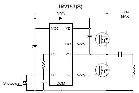
The IR2153PBF is self-oscillating half-bridge driver, and incorporates a high voltage half-bridge gate driver with a front end oscillator similar to the industry standard CMOS 555 timer. The IR2153PBF provides more functionality and is easier to use than previous ICs. A shutdown feature has been designed into the CT pin, so that both gate driver outputs can be disabled using a low voltage control signal. In addition, the IR2153PBF output pulse widths are the same once the rising undervoltage lockout threshold on VCC has been reached, resulting in a more stable profile of frequency vs time at startup. Noise immunity has been improved significantly, both by lowering the peak di/dt of the gate drivers, and by increasing the undervoltage lockout hysteresis to 1V.
Parametrics
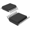
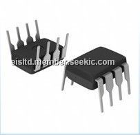
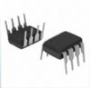
IR2153PBF absolute maximum ratings: (1)High side floating supply voltage, VB: -0.3 to 625V; (2)High side floating supply offset voltage, VS: VB -25 to VB +0.3V; (3)High side floating output voltage, VHO: VS -0.3 to VB +0.3V; (4)Low side output voltage, VLO: -0.3 to VCC +0.3V; (5)RT pin voltage, VRT: -0.3 to VCC +0.3V; (6)CT pin voltage, VCT: -0.3 to VCC +0.3V; (7)Supply current, ICC: 25mA; (8)RT pin current, IRT: -5 to 5mA; (9)Allowable offset voltage slew rate, dVs/dt: -50 to 50 V/ns; (10)Maximum power dissipation @ TA ≤ +25℃ (8 Lead DIP), PD: 1.0W; (8 Lead SOIC), PD: 0.625W; (11)Thermal resistance, junction to ambient (8 Lead DIP), RthJA: 125℃/W; (8 Lead SOIC), RthJA: 200℃/W; (12)Junction temperature, TJ: -55 to 150℃; (13)Storage temperature, TS: -55 to 150℃; (14)Lead temperature (soldering, 10 seconds), TL: 300℃.
Features
IR2153PBF features: (1)Integrated 600V half-bridge gate driver; (2)15.6V zener clamp on Vcc; (3)True micropower start up; (4)Tighter initial deadtime control; (5)Low temperature coefficient deadtime; (6)Shutdown feature (1/6th Vcc) on CT pin; (7)Increased undervoltage lockout Hysteresis (1V); (8)Lower power level-shifting circuit; (9)Constant LO, HO pulse widths at startup; (10)Lower di/dt gate driver for better noise immunity; (11)Low side output in phase with RT; (12)Internal 50nsec (typ.) bootstrap diode (IR2153D); (13)Excellent latch immunity on all inputs and outputs; (14)ESD protection on all leads; (15)Also available LEAD-FREE.
Diagrams
| Image | Part No | Mfg | Description |  |
Pricing (USD) |
Quantity | ||||||||||||
|---|---|---|---|---|---|---|---|---|---|---|---|---|---|---|---|---|---|---|
 |
 IR2153PBF |
International Rectifier |
Power Driver ICs |
Data Sheet |
|
|
||||||||||||
| Image | Part No | Mfg | Description | |
Pricing (USD) |
Quantity | ||||||||||||
 |
IR2101 |
|
IC DRIVER HIGH/LOW SIDE 8-DIP |
Data Sheet |
Negotiable |
|
||||||||||||
") |
IR2101(S) |
Other |
|
Data Sheet |
Negotiable |
|
||||||||||||
|
IR21014 |
International Rectifier |
IC DRIVER HIGH/LOW SIDE 14-DIP |
Data Sheet |
Negotiable |
|
||||||||||||
|
IR21014S |
International Rectifier |
IC DRIVER HIGH/LOW SIDE 14-SOIC |
Data Sheet |
Negotiable |
|
||||||||||||
|
IR2101PBF |
International Rectifier |
Power Driver ICs |
Data Sheet |
|
|
||||||||||||
 |
IR2101S |
|
IC DRIVER HIGH/LOW SIDE 8-SOIC |
Data Sheet |
Negotiable |
|
||||||||||||